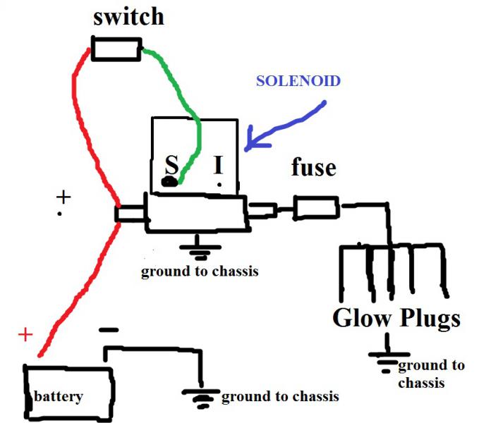
7.3 Glow Plug Relay Diagram My Wiring DIagram
7.3 Glow Plug Relay Diagram My Wiring DIagram
Originally Posted by PaysonPSD. 3 & 5 could be reversed and the relay will still operate. With key on you will see battery on both with one lead to ground. You will be reading the voltage through the winding. You need to lift the wires off the posts to isolate them and then read their potential with key on. Edit: Nice diagram Jim.

Glow Plug Relay Wiring Diagram
A wiring diagram for the glow plug relay is a diagram that shows how the electrical connections are made between the various components of the relay. The wiring diagram specifies the type of wires and their locations, as well as any additional connectors or switches. It is important to understand the correct way to wire the relay and know how.

Glow Plug Wiring Diagram 69
Joined. Mar 22, 2012. Messages. 125. Hey gus, I have a 751 with Peugeot motor, 2700 hours or so. It runs great but I've noticed the glow plug timer sometimes isn't coming on. I already have wiring and a push button run into the cab back to the relay area, where do I need to tie it in to make the glow plug relay manual with the button? Jan 2, 2016.

Glow plug control module expert information Champion
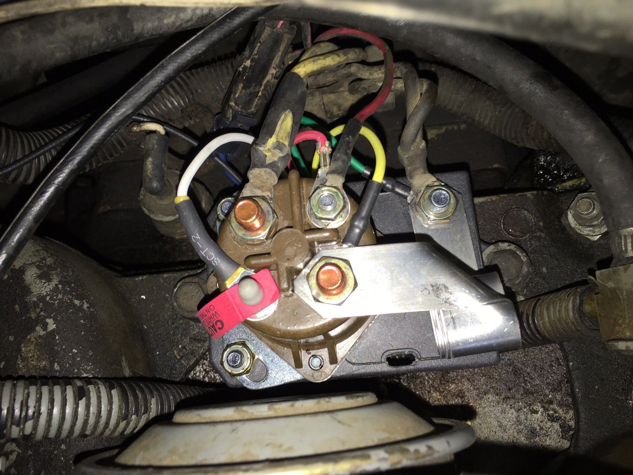
1999 - 2003 7.3L Power Stroke Diesel - Glow Plug Relay Wiring - I have a wire that is loose that I am reasonably certain goes to the GPR. Based upon the attached photo (courtesy of Guzzle7pt3.com), it is the wire that is labeled Purple Wire which is attached to the large terminal that feeds the both banks of GP's. The.

I need a wire diagram for the glow plug relay, to a 84 f250 6.9L v8 diesel
Q4 is the grounding driver for the Glow Plug relay. When Q4 is 'on', the glow plugs and indicator lamp receive power. Q4 is protected from the relay's inductive kickback by zener diode ZD1. I measured the resistance of the glow plug relay solenoid coil, and got about 72 ohms. That means that Driver Transistor Q4 will need to sink about 150-200.

Glow plug wiring diagram
Wiring diagrams are designed to provide detailed instructions and clarity on how the different components of the relay interact with each other. By following the instructions carefully and taking the necessary precautions, you can ensure that your engine runs reliably and efficiently for years to come. Glow Plug Relay Wiring Easy One The Sel Stop.
GLOW PLUG RELAY PROBLEMS Page 2 Ford Truck Enthusiasts Forums
The 7.3 glow plug relay wiring diagram consists of several components, including the glow plug relay itself, the battery, the ignition switch, the fusible link, and the glow plugs. Each of these components plays a crucial role in the proper functioning of the glow plug system. Understanding the wiring connections between these components is.
73 Powerstroke Glow Plug Relay Wiring Diagram General Wiring Diagram
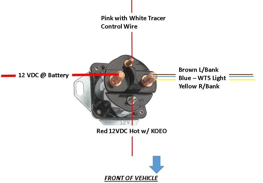
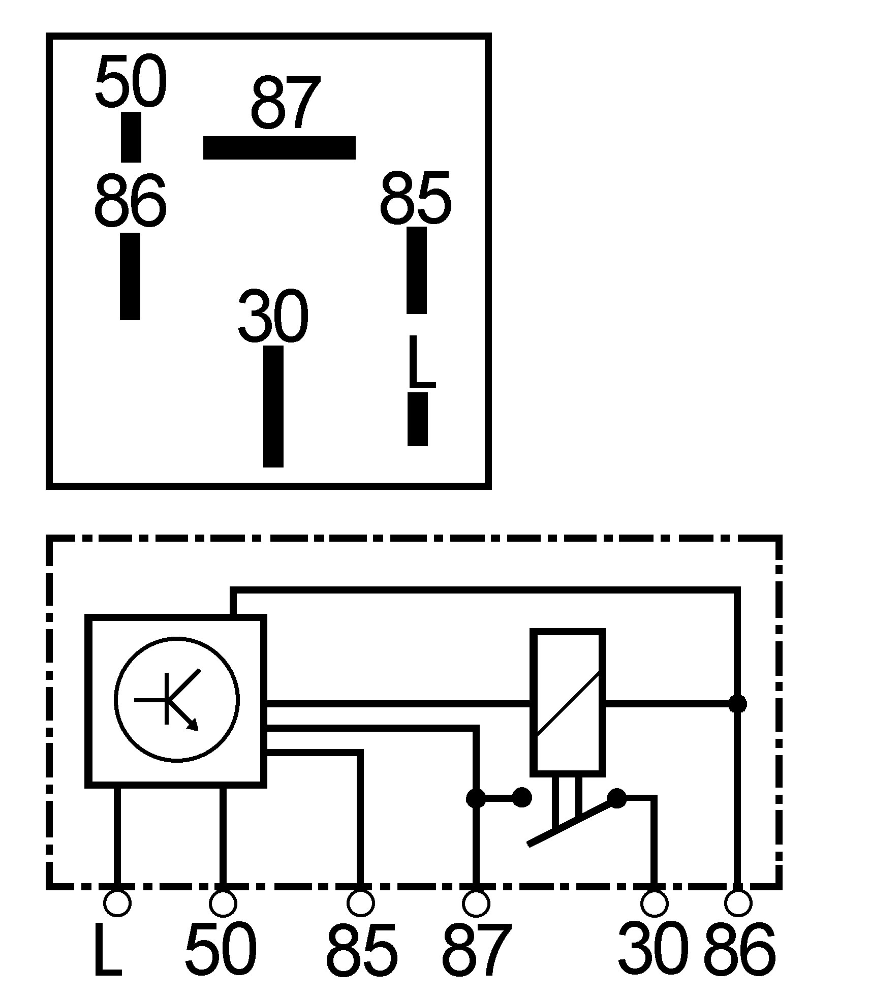
The switch is closed, sending current out pin 87 to the glow plugs (HM9) and the light micro-relay (HM99), by a voltage drop across pins 86 and 85 (left side of diagram). Turning the switch to "ignition" or "start" puts +12V at pin 86 (upper-right), so the glow plugs are triggered by sending ground to pin 85 (lower left).
7.3 Powerstroke Glow Plug Relay Wiring Diagram Cadician's Blog
EASY CONNECTION OF GLOW PLUG WIRING DIAGRAM
wiring diagram glow plug relay 73
Below is a 7.3 Powerstroke glow plug relay wiring diagram. Ref: 3 Best 7.3 Glow Plug Relay Reviews WHITE RODGERS 586-902 CONTACTOR. Check Price On Amazon. First up on our list is the White Rodgers 586-902 contactor. We replaced a 99 F250 7.3 stock relay with this one. And while it does not come with a wiring diagram, the installation was pretty.
7.3 Powerstroke Glow Plug Relay Wiring Diagram Database
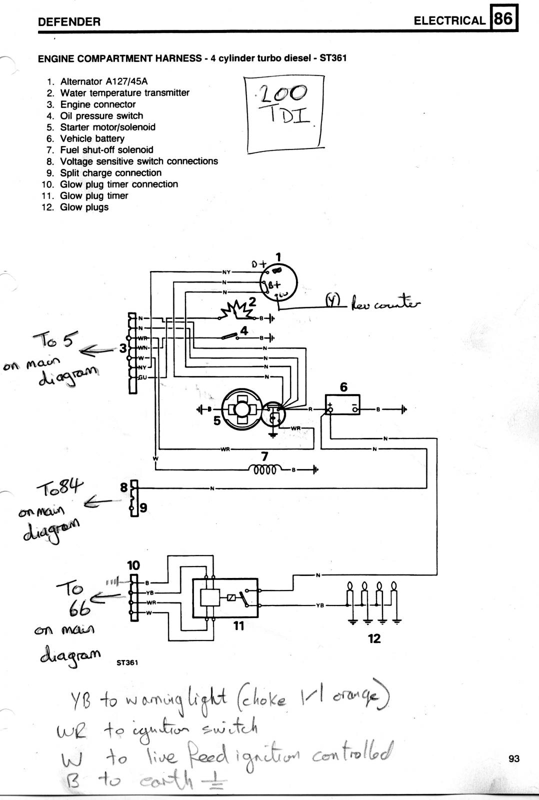
Electrical Systems, "Glow Plug System" Operation begins on page 8-12 (pg244). Figure 8-12, Glow Plug Electrical System Diagram Figure 8-15, Glow Plug System- Relay Wiring Figure 8-16, Glow Plug System- Controller Power Figure 8-17, Glow Plug System- Input Wiring Figure 8-18, Glow Plug System Cycling- Before Cranking
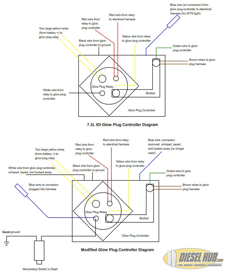
7.3L IDI Manual Glow Plug Controller/Switch Wiring
BERU's glow plug control unit uses three-phase technology to ensure optimal performance of your glow plugs: Phase 1: pre-heating initiated when the ignition starts. Glow plugs are quickly heated up to 1300° Celsius. Phase 2: Heating during starting to ensure optimal combustion of your fuel. Phase 3: Post-heating.
25 7.3 Powerstroke Glow Plug Relay Wiring Diagram Wiring Database 2020
The glow plug timer relay is wired to the engine's main power source and connected to the glow plugs. It provides a controlled voltage to the glow plugs, allowing them to heat up and ignite the fuel-air mixture in the engine. The wiring diagram contains all the information needed to connect the relay to the engine's power source, as well as the.

2002 7.3 Powerstroke Glow Plug Relay Wiring Diagram Database
In the intricate dance of a diesel engine, the glow plug relay plays a pivotal role, ensuring a harmonious start even in the coldest of winters. Just like a conductor synchronizing the orchestra, the glow plug relay wiring diagram guides the flow of electricity, illuminating the dark alleys of engine ignition. Let's venture into the enchanting realm of this diagram and uncover its mystical.
44 Beautiful Glow Plug Relay Wiring Diagram
Creating a wiring diagram for a glow plug timer relay is a relatively straightforward process. All that is needed is a voltmeter, wire strippers, and some basic wiring diagrams. Begin by locating the terminal points on the glow plug timer relay and using the voltmeter to check the voltage. Once the voltage rating of the parts is known, the.
Glow Plug Relay Wiring Schematic
A wiring diagram for a glow plug relay is typically a simplified version of the electrical connections that are made. It shows the components of the circuit as simplified shapes and the signal connections between them. The pictorial representation of a wiring diagram makes it easier to understand how the relay works and how it is connected to.
